User Tag List

Likes Likes:  0
Results 1 to 9 of 9

Thread: Whacking the hornet's nest

  1. #1
    Join Date
    Dec 2009
    Location
    Tennessee
    Posts
    132
    Post Thanks / Like
    Mentioned
    0 Post(s)
    Tagged
    0 Thread(s)

    Default Whacking the hornet's nest

    With all respect-

    I build trials bikes. Its all balls-n-balance. No such thing as a shimmy. Wheels rarely make a revolution. Alignment in terms of eyeball-

    I am building a cross bike. My first bike where 'precise' alignment is more of a necessity . I have a new surface plate (love it) although my gripe begins........

    Playing around with a frame on the surface pate has given me the opportunity to really see the interactions of each tube: one to another. Truly fascinating to a bike geek. Also makes me more of a skeptic on the frame alignment issue.

    I'm using a dial indicator and am pushing tubes around in the 10 thousandths range. Even when I push things around in the 20-30 thousandth range, its so teny tiny.

    I am certain when your throw a leg over a bike, just being on it moves the frames in the above ranges. Certainly pedaling does. Certainly the deflection in the tires and spokes is more than this.

    So how straight is straight or is it simply relative? Is it really a marketing hype among builders?

    If I'm bombing down a road, isn't my bike and it components fluctuating more than a few thousandths? I know in trials riding, I'm bending frames way outside these ranges.

    So, to all the VS effers: How straight is straight. I hear of builders taking about absolute straight but isn't that like kicking a deck chair off the Queen Mary?

    What is acceptable?

    I can go crazy trying to get the needle not to move-

    Hey thanks VS.

  2. #2
    Join Date
    May 2008
    Location
    Better to be ruined than to be silent atmo.
    Posts
    22,147
    Post Thanks / Like
    Mentioned
    24 Post(s)
    Tagged
    0 Thread(s)

    Default Re: Whacking the hornet's nest

    well i cannot find the archived post that addresses this so i'll reiterate here atmo. see the images below - they are from my old shop and maybe 6-7 years ago. every point gets measured: the seat tube over its length, the linearity of steering axis, the steering axis opposing the bio-mechanical axis, the rear hub's placement, and the way a wheel sits in the frame. the ideal is for every point to be where it should. my ideal is that an as-is brazed frame, after machining, should be too. but my reality is that i will allow a measured point to deviate up to a mm, OR i will allow all deviations to add up to a mm. i am not a cold setting proponent, so if the points cool into a place that yields what i want, it stays there. the exception is dropouts. if the rear wheel is visibly over by a mm after i assemble the rear triangle, i file up the longer (seat stay) side so that it is dead center atmo. caveat - my frames will look different on your table. my frames will look different on my table if i invert them. and, if anyone ever takes a facing tool to one of my frames once it passes my table's smell test, he has essentially altered all the dimensions i measure, and all bets are off.


  3. #3
    Join Date
    Feb 2009
    Location
    Noblesville, Indiana, United States
    Posts
    1,799
    Post Thanks / Like
    Mentioned
    0 Post(s)
    Tagged
    0 Thread(s)

    Default Re: Whacking the hornet's nest

    Very well put.

  4. #4
    Join Date
    Dec 2009
    Location
    Tennessee
    Posts
    132
    Post Thanks / Like
    Mentioned
    0 Post(s)
    Tagged
    0 Thread(s)

    Default Re: Whacking the hornet's nest

    e-RITCHIE

    Thanks for the insight. I'm a little surprised there hasn't been more input on this topic (aside from the archive, if I can find it), but I can understand that it might be a touchy area for many.

    Thanks again VS-

  5. #5
    Join Date
    May 2008
    Location
    Better to be ruined than to be silent atmo.
    Posts
    22,147
    Post Thanks / Like
    Mentioned
    24 Post(s)
    Tagged
    0 Thread(s)

    Default Re: Whacking the hornet's nest

    Quote Originally Posted by 3wfab View Post
    e-RITCHIE

    Thanks for the insight. I'm a little surprised there hasn't been more input on this topic (aside from the archive, if I can find it), but I can understand that it might be a touchy area for many.

    Thanks again VS-

    craig ryan once showed me an archived post of mine that addresses my assembly sequence.
    but, alas - i cannot locate that one either atmo.

  6. #6
    Join Date
    Feb 2009
    Location
    Noblesville, Indiana, United States
    Posts
    1,799
    Post Thanks / Like
    Mentioned
    0 Post(s)
    Tagged
    0 Thread(s)

    Default Re: Whacking the hornet's nest

    Richard,
    You posted a nice response on the email list once, maybe 4-6 years ago, and I think it's what you are referring to. I'm not sure of the date anymore, but you were replying to MManning and I'm sure there were other emails related to it. I don't think it's been altered except through formatting. This is a nice companion to your recent Tulsa photo series which also has some good description within it. As a note, there is a whole lot of intuition and lots of brain cells between the lines of the words below. A couple of the words may be chopped off, but the intent remains.
    Craig
    ---------------------------------
    Richard's sequence

    only after the tube cuts are all made do i drill through all lugs into a ll tube, thus ensuring after all the checks and balances are made in the fixture that the interference fits are as "at rest" within each lug and in as "as assembled into a main triangle" sequence as they can be.
    after all parts are drilled and pinned, the pins are more like dowels than replacements for said fixture, but i do use far fewer clamps on the fixture once the parts are pinned, reassembled in the fixture, and fluxed ready to tack, etc. i am a believer that the material is the weak link in the process and one can only hope to use good fixturing, sequencing, and intuition in order to make a straight frame from pipes that carry a margin of error as a matter of course. and that opinion also is tethered to the fact that heat affects metal, particularly when metal is forced against neighboring metal, as is the case when a frame is assembled. It's necessary to find a method that works for you and you alone based on the tooling available and your skill set to date.

    most joints have two pins in each pipe as a matter of course. on my frames, sometimes i get ambivalent and use one per pipe (especially if i am low on pins and or breaking drill bits) but nearly all the dt to bb sockets have the three pins. iow, i know what is yielded in my own process, so two pins vs three won't change the results i have come to realize.

    at the "let's go" time, the entire main triangle is cleaned, fluxed, and checked in the hydra fixture. if i am still happy with what is in front of me, i drive the pins in so they "wedge", and then i remove this unit and put it on my m+l table. i then lightly tack the seat tube to the bb at a perfect reading. when cool, i take the main triangle and put it BACK into the hydra fixture and use only the head tube cones to center the front to the back (head tube to seat tube). then, i tack the front lips of the two head lugs, and also the top point on the bottom lug and the back-of-head-lug point on the top lug.
    after cooling, i return the unit to the m+l table and verify 1) that the seat tube is STILL at "zero" and 2) i use a lightweight head tube check bar to verify that the steering axis is at "zero" too. if the steering axis is askew, even though the head lugs are tacked, i can 'tweak" the measurement because the front triangle assembly can STILL move within 1) the seat lug and 2) the down tube port of the bb shell. no matter, once the steering axis is at "zero", i then tack one area of the seat lug whilst the frame is still on board the m+l table because i do not want to manhandle it and change any setting. with this all done, the ONLY non-tacked area is the down tube to bb shell port. that comes later.

    i then 1) braze up the head lugs and let cool, 2) wash off flux, and 3) check linearity again. if something in the steering axis er, drifted, i can still correct for a thou or three by turning the lighter head tube rod checker within the head tube, and the correction comes because the down tube still has area in which to rotate within the bb shell port. if all is then copasetic, i braze the seat lug. if all stays copasetic, i place the unit back on the m+l table and tack the down tube to the bb shell so that the steering axis is directly in front of the biomechanical axis (i.e., the seat tube). then i braze up the bb shell in one fell swoop.

    note to self - up until a year ago, my sequence was different; i used to attack the bb shell assembly first and then would continue on to the head lugs and then on to the seat lug. i cannot recall why i considered changing, but did, and i am content with the net results. oh, and yes - at the end of all the pre-checks that precede any tacking to begin with, the fixture points, especially the clamps, are in their loosest state. the fit-ups and the pins do the job at that point. i should have noted this earlier.

    4) the gap in the chain stay to bb socket is an illusion in these pics. i fear that i shot the image(s) when the parts were pinned but the seat stays were not yet pinned to the seat lug. had this been the case, that "gap" would have closed as the rear triangle's interior angle would become more acute.

    i hope the text helps.

    e-RICHIE

    ------------------------------
    Last edited by Craig Ryan; 11-05-2010 at 08:48 PM.

  7. #7
    Join Date
    May 2008
    Location
    Better to be ruined than to be silent atmo.
    Posts
    22,147
    Post Thanks / Like
    Mentioned
    24 Post(s)
    Tagged
    0 Thread(s)

    Default Re: Whacking the hornet's nest

    did i do all that upper case atmo?
    whoa - mark the calendar...


    Quote Originally Posted by Craig Ryan View Post
    Richard,
    You posted a nice response on the email list once, maybe 4-6 years ago, and I think it's what you are referring to. I'm not sure of the date anymore, but you were replying to MManning and I'm sure there were other emails related to it. I don't think it's been altered except through formatting. This is a nice companion to your recent Tulsa photo series which also has some good description within it. As a note, there is a whole lot of intuition and lots of brain cells between the lines of the words below. A couple of the words may be chopped off, but the intent remains.
    Craig
    ---------------------------------
    Richard's sequence

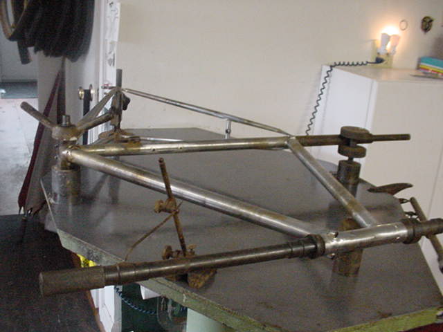
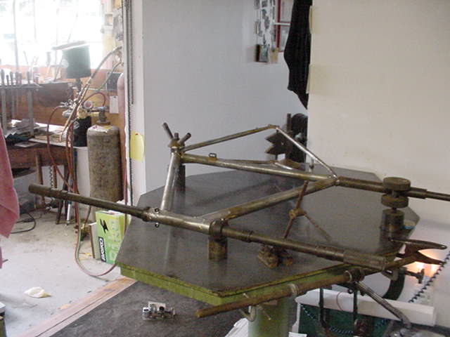
    Only after the tube cuts are all made do I drill through all lugs into a ll tube, thus ensuring after all the checks and balances are made in the fixture that the interference fits are as "at rest" within each lug and in as "as assembled into a main triangle" sequence as they can be.
    After all parts are drilled and pinned, the pins are more like dowels than replacements for said fixture, but I do use far fewer clamps on the fixture once the parts are pinned, reassembled in the fixture, and fluxed ready to tack, etc. I am a believer that the material is the weak link in the process and one can only hope to use good fixturing, sequencing, and intuition in order to make a straight frame from pipes that carry a margin of error as a matter of course. And that opinion also is tethered to the fact that heat affects metal, particularly when metal is forced against neighboring metal, as is the case when a frame is assembled. It's necessary to find a method that works for you and you alone based on the tooling available and your skill set to date.

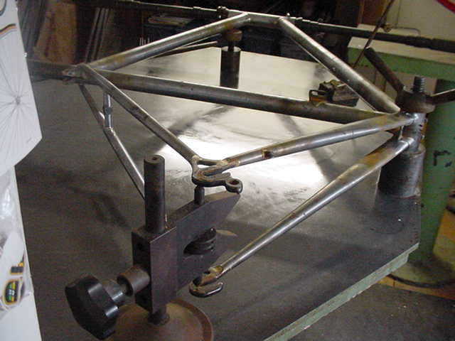
    Most joints have two pins in each pipe as a matter of course. On my frames, sometimes I get ambivalent and use one per pipe (especially if I am low on pins and or breaking drill bits) but nearly all the dt to bb sockets have the three pins. iow, I know what is yielded in my own process, so two pins vs three won't change the results I have come to realize.

    At the "let's go" time, the entire main triangle is cleaned, fluxed, and checked in the hydra fixture. If I am still happy with what is in front of me, I drive the pins in so they "wedge", and then I remove this unit and put it on my M+L table. I then lightly tack the seat tube to the bb at a perfect reading. When cool, I take the main triangle and put it BACK into the hydra fixture and use only the head tube cones to center the front to the back (head tube to seat tube). Then, I tack the front lips of the two head lugs, and also the top point on the bottom lug and the back-of-head-lug point on the top lug.
    After cooling, I return the unit to the M+L table and verify 1) that the seat tube is STILL at "zero" and 2) I use a lightweight head tube check bar to verify that the steering axis is at "zero" too. if the steering axis is askew, even though the head lugs are tacked, I can 'tweak" the measurement because the front triangle assembly can STILL move within 1) the seat lug and 2) the down tube port of the bb shell. No matter, once the steering axis is at "zero", I then tack one area of theseat lug whilst the frame is still on board the M+L table because I do not want to manhandle it and change any setting. With this all done, the ONLY non-tacked area is the down tube to bb shell port. That comes later.

    I then 1) braze up the head lugs and let cool, 2) wash off flux, and 3) check linearity again. If something in the steering axis er, drifted, I can still correct for a thou or three by turning the lighter head tube rod checker within the head tube, and the correction comes because the down tube still has area in which to rotate within the bb shell port. if all is then copasetic, I braze the seat lug. If all stays copasetic, I place the unit back on the M+L table and tack the down tube to the bb shell so that the steering axis is directly in front of the biomechanical axis (i.e., the seat tube). Then I braze up the bb shell in one fell swoop.

    Note to self - up until a year ago, my sequence was different; I used to attack the bb shell assembly first and then would continue on to the head lugs and then on to the seat lug. I cannot recall why I considered changing, but did, and I am content with the net results. Oh, and yes - at the end of all the pre-checks that precede any tacking to begin with, the fixture points, especially the clamps, are in their loosest state. The fit-ups and the pins do the job at that point. I should have noted this earlier.

    4) the gap in the chain stay to bb socket is an illusion in these pics. I fear that I shot the image(s) when the parts were pinned but the seat stays were not yet pinned to the seat lug. had this been the case, that "gap" would have closed as the rear triangle's interior angle would become more acute.

    I hope the text helps.

    e-RICHIE

    ------------------------------

  8. #8
    Join Date
    Feb 2009
    Location
    Noblesville, Indiana, United States
    Posts
    1,799
    Post Thanks / Like
    Mentioned
    0 Post(s)
    Tagged
    0 Thread(s)

    Default Re: Whacking the hornet's nest

    What upper case? You have to fix your copy...

  9. #9
    Join Date
    May 2008
    Location
    Better to be ruined than to be silent atmo.
    Posts
    22,147
    Post Thanks / Like
    Mentioned
    24 Post(s)
    Tagged
    0 Thread(s)

    Default Re: Whacking the hornet's nest

    Quote Originally Posted by Craig Ryan View Post
    What upper case? You have to fix your copy...
    quelle dommage atmo.

    (french for what cheese...)

Bookmarks

Bookmarks

Posting Permissions

  • You may not post new threads
  • You may not post replies
  • You may not post attachments
  • You may not edit your posts
  •