Dear Guest,
Please register or login. Content don't create itself!
Thank you
-
 ISO4210_6 Tester development Part 1.
One of the many hurdles faced when doing something new is to try to prove that its safe and reliable. In the bicycle world a reasonable proxy for this is to pass ISO 4201, of which Part 6 is relevant for road frames. If you are seriously interested in this youll have to buy the specification from your national standards organisation but if your interest is only casual you can refer to the older EN 14781 - the ISO simply adopted the EN as usual.
Im concentrating on the pedalling forces fatigue test first as that seems to be the hardest to pass. If you have a look at the standard linked above youll see that this test requires the pedalling forces to be applied at an angle of 7.5 degrees from the vertical to a point 150mm out from the centre line on a pair of 175mm cranks each pointing downwards and forwards at 45 degrees. The force, specified at 1100N, is applied to each pedal 100,000 times: roughly the equivalent of Marcel Kittel unleashing his stage finishing sprint and then doing it again 8,000 times.
Since I dont have a Marcel Kittel on hand Ill have to substitute air cylinders, a quick look through the manufacturers specs suggests that with a practical max pressure of 700 kPa Ill need a 50mm diameter cylinder. Since the 1100N is applied at 150mm at 7.5 degrees that computes to a net torque of 163 Nm. This should mean that the net deflection at the cylinder is fairly small but in practice all the joints specified by the ISO method allow the frame to move in the jig, so a stroke length of about 50mm is required.
In theory I could rely on the product of air pressure and cylinder area to achieve the specified 1100N but I decided to instrument the set-up with a pair of strain gauge force transducers so I could be sure I reached the spec. Although button style transducers would be easier to accommodate I found a pair of 2500N beam style transducers complete with calibration certificates available locally so I bought those and made some adapters to allow them to work with the simple thrust force as specified. I had initially planned to fabricate my own strain gauge amplifiers to interface the transducers to the PLC but again I found a couple of commercial units off the shelf for a good price so I bought those.
I went into this expecting to have to deal with an industrial spec PLC and progam in ladder logic (yes Im old enough to remember how to do ladder logic). Whilst looking for a suitable PLC I came across the new Velocio ACE PLCs These things are as cheap as chips so I thought I would give one a go: with digital only inputs they are as low as $USD50 each, I needed analogue input capability to handle the output of the strain gauge amplifiers so I ended up with a higher model, even so it was $USD150.
That price includes integrated software for programming via a USB cable. With industrial units the programming software and interface kit is usually an expensive add-on, on the theory that the end user usually doesnt need it. I was even more pleasantly surprised to find that besides the unit being fully compatible with ladder logic it also has a native graphical flowchart programming interface. I learnt enough of this to get myself into trouble: the programs basically worked but had small flaws that needed debugging: as an example I included what I thought was a simple step counter that would tell me how many cycles the machine has performed on any given test and I simply couldnt get it to count. Fortunately the online help people at Velocio are both very good and very patient, they soon had the programs running the way I wanted (it turned out I had too many instructions on that state line so the program was ignoring the last one which happened to be the counter).
If this sounds like a bit of a rave, it is. Ive worked with many industrial scale units and within its I/O capabilities this things trounces the lot of them for ease of setup and use, whilst being a fraction of the price. If I needed more I/O capabilities than this unit has (12 analogue in, 12 digital in, 12 digital out) Id look at one of their Branch units, as the name implies these can be set up as a branched distributed controller.
One caveat: if I did this again, Id be very tempted to change to one of the Ace embedded PLCs and use it to make a single board solution encompassing the strain gauge amps, coil drivers and power supplies.
A minor complication is that the PLC uses open collector outputs with a 200 mA current limit. Since that was below the peak current draw of the 12V solenoids for the pneumatic actuators I wanted to use, I decided to implement a MOSFET interface to protect the PLC outputs. An alternative would have been to use 24 volt solenoids in the actuators which would halve the current load: the PLC outputs can handle up to 30V DC.
These were all mounted in a simple Hammond 155 series aluminium enclosure. Since the load cells require a four wire interface I used a single D9 subminiature connector for both. The interface for the coils is a JIS 4 pin microphone connector. These were both chosen because they are simple, reliable and cheap.
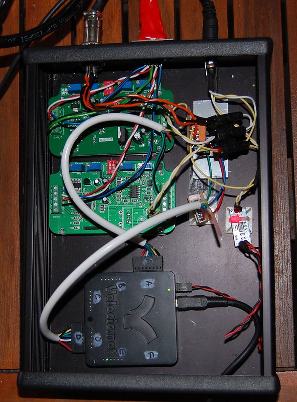
Control Box_2
More on the physical construction next up.
Mark Kelly
Similar Threads
-
By Boedie in forum Smoked Out
Replies: 30
Last Post: 11-22-2014, 05:45 PM
-
By magnoliacycles in forum Smoked Out
Replies: 25
Last Post: 04-11-2011, 04:57 PM
 Posting Permissions
- You may not post new threads
- You may not post replies
- You may not post attachments
- You may not edit your posts
-
Forum Rules


 Likes:


 Reply With Quote
Bookmarks