

 Likes:


The last one was long on words and short on maths, this one is long on both. Bear with me, there are some interesting figures at the end.
In the screed above I’ve mentioned that I have a great deal of latitude on several processes that affect the torsional and bending stiffnesses of the tubes, such as the number, fibre type, winding density and winding angle of the carbon layers and the number, wood type, grain direction and radial orientation of the wood layers . This allows me to design each tube to suit its intended purpose, which is a nice statement but what does it actually mean?
Basically it means that I establish design criteria for a given tube, then I try to make a tube that fits the criteria chosen. Generally, one criterion is to make the lightest tube that satisfies the other design criteria but this is not definite, for instance on my wife’s bike she was happy to accept a 20g weight penalty to allow the inclusion of a wood that has emotional significance to her.
The other design criteria naturally depend on where the tube is going to be used; to keep this simple but reasonably illustrative I will focus on the criteria for a typical road bike top tube. For a tube like this I am looking for torsional and lateral bending stiffnesses that result in an appropriate degree of front end torsional stiffness for the frame as a whole, lateral stiffness that is appropriate for the rider’s weight and aggressiveness and a high ratio of lateral to vertical stiffness.
To assist with this process, I’ve set up a design spreadsheet that calculates the mass and the contributions to torsional stiffness and the lateral and vertical beam stiffnesses of each layer or part layer using the moduli given in the graphs in part one of this series. This involved a bit of calculus as none of the standard sources give a moment of inertia for a tube with the sides sliced off, so I had to calculate that myself . Since others might find this useful, I’ve included the formulae I use below.
Sections
“J” is the rotational moment of inertia, “Ixx” is the moment of inertia about the X axis etc.
As a reality check: as r -> R, (R^2 + r^2)/2 -> r^2 ,
so 0.410.A/2.(R^2 +r^2) + 0.090.A/2.(R^2 +r^2) = A/4 . r^2
which is the classic formula for the moment of inertia of an infinitely thin hoop.
The spreadsheet then adds all the contributions to give a total calculated value for torsional, lateral and vertical stiffness of the tube.
The model I use for relating these individual tube stiffnesses to the stiffness of the frame as a whole is probably a little simplistic but it seems to achieve a reasonable fit to reality. I can’t afford FEA and it apparently copes badly with organic materials on the small scale so this is as good as you are going to get. For the front end stiffness, I simply sum the contributions from torsional stiffness and beam stiffness of each of the top tube and down tube. This is based on the following thought experiment:
Imagine the top tube is rigidly joined to the head tube but the down tube connected via a ball and socket joint so it can swivel. To twist the head tube away from the seat tube axis by a given degree then requires overcoming the torsional stiffness of the top tube in series with the lateral beam stiffness of the down tube. Symmetry requires that the same thing will obtain with the positions reversed, so the four factors TT torque, DT beam, DT torque and TT beam are summed to give the frame tubes’ contribution to front end stiffness.
Note that this does not account for the contribution of the joints to the headtube or the headtube itself. In practice calculating the figures on the “free length” of the tube eg the length between the actual joints yields overall stiffness figures which seem close to the real world frames tiffness. In the future I hope to refine this but that will wait until I build the frame fatigue / stiffness testing rig later this year.
Evaluating the contribution of the torsional stiffness of each tube is simple, just apply the known formula for angular deflection:
Θ = T L / J G,
Rearranging gives :
T / Θ = J . G / L
eg for a given torque and a given product of rotational moment of inertia and shear modulus, the net deflection will be proportional to tube length. This seems intuitively obvious.
Please note that Θ will be in radians and the formula assumes the torque is applied along the axis of the tube. If the torque is applied off axis we can simply multiply by the sine of the angle between the torque force couple and the tube axis.
Evaluating the contribution of the beam deflection of each tube is a little more complex, fortunately we have the great Leonhard Euler on our side. He observed that the angular distortion of each section will be proportional to the torque on that section, which is in turn proportional to the ratio of tube length to moment of inertia; all these sections add so the total angular displacement is proportional to the distortion per section times the length and finally the net linear displacement is the integral of these angular displacements over the length. Euler’s formula for a point loaded cantilevered beam is:
Δ x = F . L^3 / 3 . E . I.
Now consider the headtube with a length between tube junctions of Y.
A torque T will produce a force couple F acting at distance Y, so
T = F.Y or F = T/Y
A deflection of Δ x at one end of the tube is equivalent to an angular deflection of
Δ x / Y, so
Θ = Δ x / Y or Δx = Θ . Y
Substituting these into the formula above gives
Θ . Y = T/Y . L^3 / 3 . E . I.
rearranging gives
T / Θ = Y^2. 3 E I / L^3.
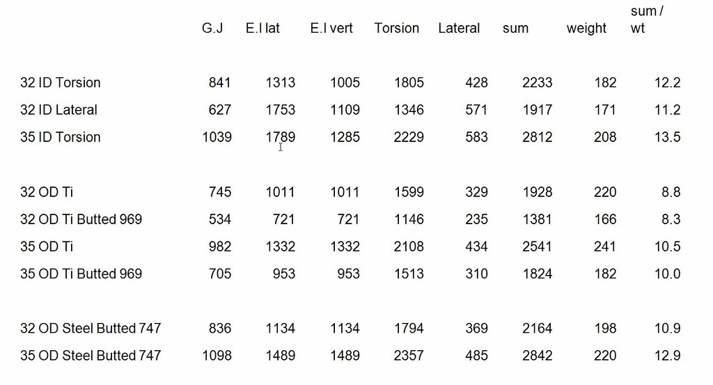
To see who this works in practice, here are the calculated stiffnesses for some tubes. These were options for the top tube on a bike for a fairly large rider (that would be me). To give you an idea of how these figures stack up against other materials, I have included figures for tubes of other materials:
Figures


 Reply With Quote
Bookmarks