Dear Guest,
Please register or login. Content don't create itself!
Thank you

Likes:
0
-
 crown design
I was going to post this on FNL.. but I feel I should show the design here instead.. I need a gut check concerning the design and am asking you fine folks to offer thoughts if you feel so inclined.
I will share the thoughts I have later, but for now I feel that I am thinking too much about it.
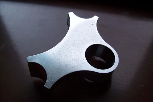
The crown is designed for 25.4mm round blades .9/1.3 wall and 25.4mm threadless steerer. I plan to use a SON20 disk compatable dyno. Cut from 1" 1018 plate. This crown is for a Chicago style winter bike I am designing. If it turns out to be a faulty design then I will start over... not proud here!
Thank you for your time,
CWN
-
here is the design
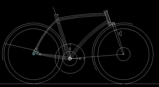
Bent tubes mean strait gauge CroMo.. .035" wall for front triangle. Wishbone SS, bent deda CS's.
"he ain't heavy, he's my brother"
-
I think you'll have a major stress transition at the forkleg-crown junction, beginning at the rear corner. I'd make the tang a lot longer and friendlier, and use a large shaped plug inside to stiffen the tube.
-
If you CNC'd the thing lets see what it takes one to fail and lets see how it fails.
That being said, I might try to radius a few of those corners to avoid stress risers.
Also...D. Kirk has done a bunch of destructive testing in a past life and would be a particularly good person to ask.
-
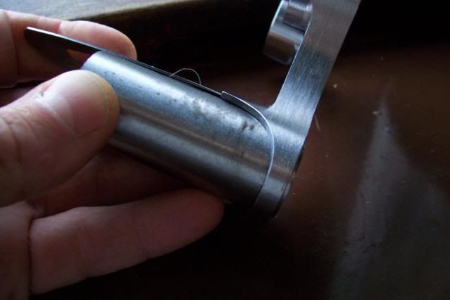
revise+ modifications
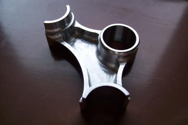
plates plus coping.. gonna do some final fitting (file coping) once the steerer is in. The plates are a bit sloppy right now because I did not allow for spring back.. just wanted to rail them out to see if the plates would work. gonna make some new dies to dial the press forming. Just working to get it right and minimize the stress lines as best I can.
CW
-
Really impressive! Do you have any pics of the machining?
Thanks, Joel
-

Originally Posted by
creighton

plates plus coping.. gonna do some final fitting (file coping) once the steerer is in. The plates are a bit sloppy right now because I did not allow for spring back.. just wanted to rail them out to see if the plates would work. gonna make some new dies to dial the press forming. Just working to get it right and minimize the stress lines as best I can.
CW
That's a lot of progress in a short time!
-
Sorry Joel..
No process/machining pics. Soooo I hope a verbal description is okay..
From the start I used AutoCad to lay out the design in three views.. working though the machining mentally as I drew it up. Then the DWG file went into MasterCam for tool path generation. Because there was no easy way to hold onto the thing I cheated.
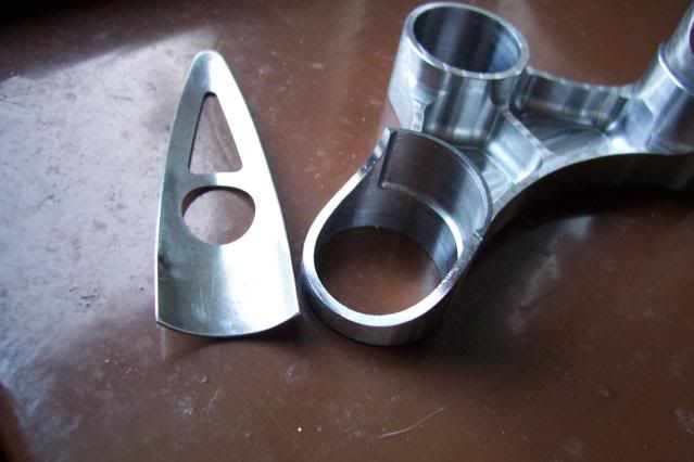
I found a chunk of hot rolled 1" thick 8620 steel alloy plate and clamped into the vice over a set of parallels. The part zero/zero through it all was the bore for the steerer. The machining was all done in a HAAS VF-1 with flood coolant. I cut all of the multi level planes first, then the bores and pockets. The last cut was the profile. In order to keep the profile clean and prevennt the part from throwing itself into the tool. I set the cut depth to leave .005" of flashing. Thus the sanded surface all around the finished part.
Then I went over the ProtoTrak Bridgeport and created the blade pockets and blade copes in the sleeves... I used a 'V' jaw on the solid side of the vice with a flat jaw on the movable side.. again set onto parallels. This will flex the bore walls a bit. However the steerer bore was not touched again. this step was the create the blade pockets. I left some flow gap for the silver so the slightly flexed bore of the fork sockets did not care. It came out true and the blades nested well.
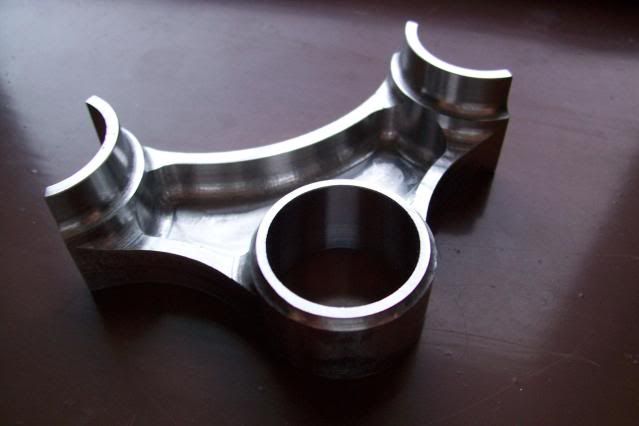
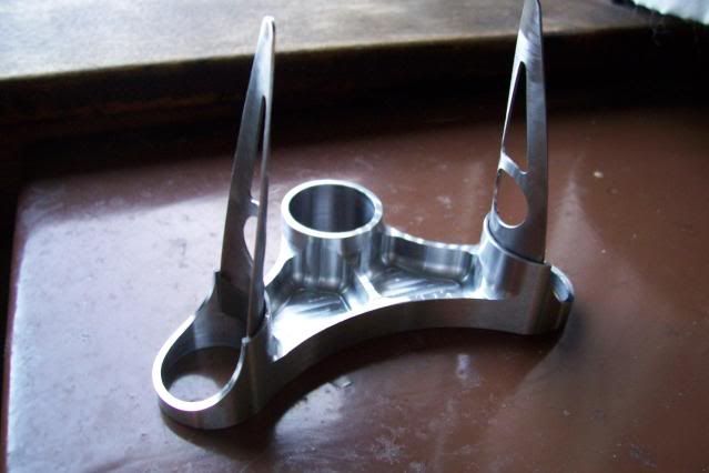
For the blade socket copes...
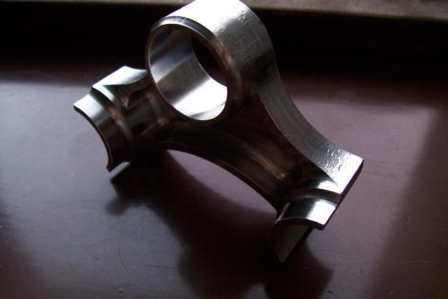
The 'V' jaw was switched out for a matching flat jaw. Again parallels... At this point the sockets were still fully cylindrical and at the original 1" plate thickness dimention. The crown was then slid over past the side face of the jaw so the tool would barely clear moving along its chosen path. A radius was programmed and then cut. The part was then rotated 180 deg. the tool path was mirrored along the X axis thus the second cope.. DONE!!! whew... Through it all I concentrated on NOT pushing the wrong 'go' button.. all that work only to eff it up in the last 5 minutes.. been there too many times before! Machines are brutal in the fact they are VERY dumb and dont care what you are thinking you want them to do... they go to home coordinates and fast. A 'click' is all it takes.. the carbide tool crashes into the part, gouges, breaks and.... well... as they say in the old country "thats that".
Two days machining and figuring.. expensive crown indeed! Anouther one would take about half the time... lots of steel that isn't there anymore. Still though in light of that.. $$$$
Finish total weight is 4.6 oz. Burly indeed but not too bad for a low and slow Chicago, worst case scenario winter bike. with 8620 I could go thinner with the pocket and bore walls. I might be able to get it down to 3+ oz.
CW
-
Nice CNC work, the underside relief is really classy. Neat lines on the frame design too!
-
a shelf for the blades?
or
with out the shelf one can
cut the blades roughly over length
fit up the blades
pin and braze
trim proturding blade
question, are you pluging the top of the blade?
-
Thanks for the comments! Yeah Dazza, gonna cap the blade 'tops' with a brass button of some sort...
-
Originally Posted by
creighton
Thanks for the comments! Yeah Dazza, gonna cap the blade 'tops' with a brass button of some sort...
would "atmo" badges fit 
-
 Posting Permissions
- You may not post new threads
- You may not post replies
- You may not post attachments
- You may not edit your posts
-
Forum Rules


 Reply With Quote

Bookmarks